Programmable Audio Player
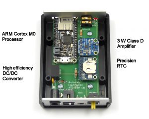
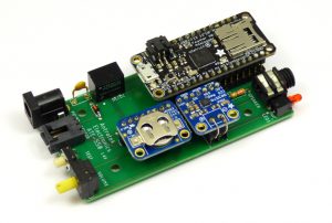
This is your ultimate and complete audio player. It is a fully open source, programmable player with a powerful ARM Cortex M0 processor and included 3W amplifier. The player is complete with microSD card reader, sensor input, test button, programmable led and a 10-position switch (which you can use for volume setting, mode select or any other purpose). To make it even more versatile, the player has an RTC to give you the possibility to play your audio at certain times and dates. The audio player is designed to fit in a standard enclosure. Front and back panel are available.
You can use this player for many different applications, such as doorbell with different sounds, burglar alarm, storytelling when entering a room, talking garbage can, animated sounds, talking clock, etc.
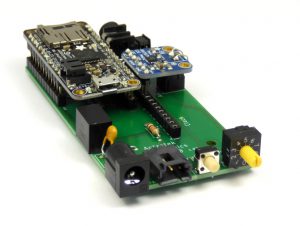
The player is affordable and easy to build. The design consists of a carrier board on which you can plug-in readily available modules from Adafruit.
With Arduino IDE you can program the player and on the microSD card you can store the audio files in WAV format.
Carrier Board
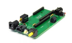
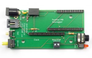
The Audio Player Carrier Board (Antratek ATE-550) is complete with connectors, switches, components and a DC/DC converter.
Assembly
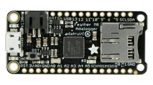
The Feather M0 Adalogger (Adafruit Product ID: 2796) is an ‘all-in-one’ Cortex M0 data logger (or data reader) with built-in USB connector and LiPo battery charger. It’s an Adafruit Feather M0 with a microSD holder. The heart of the Feather M0 is an ATSAMD21G18 ARM Cortex M0 processor clocked at 48 MHz and with 3.3V logic, the same one used in the Arduino Zero/M0.
It has an I2S bus and an SD card holder with its own SPI interface with which you can play audio files. I2S (not to be confused with I2C) is a digital audio protocol used to exchange audio data between chips. The Arduino Sound Library is available to play and analyze audio data.
Adalogger supports microSD cards up to 32GB.
You can use the included header connectors to solder on the Feather module and plug it into the carrier board.
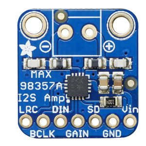
The MAX98357 I2S Amp Breakout (Adafruit Product ID: 3006) takes standard I2S digital audio input and, not only decodes it into analog, but also amplifies it directly into a speaker. This small mono amplifier is surprisingly powerful – able to deliver 3.2 Watts of power into a 4 ohm impedance speaker.
Solder the included header on the module, but do not use the terminal block. In stead solder two bare wires on top and screw these wires on the terminal block of the carrier board.
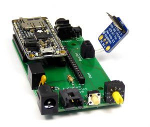
The RTC module is optional. If you want to play audio which is time dependent, you can add this module.
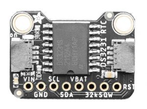
DS3231 Precision RTC (Adafruit Product ID: 5188) is a compact, breadboard-friendly breakout. It has an extremely accurate I2C-integrated Real Time Clock (RTC) with a Temperature Compensated Crystal Oscillator (TCXO). With a CR1220 12mm coin cell (not included) plugged in, you can get years of precision timekeeping, even when main power is lost.
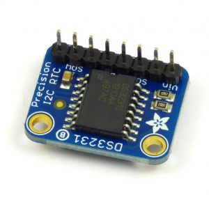 For the Audio Player you can use the DS3231 module with or without STEMMA QT/Qwiic connectors.
It is important you plug it upside down into the Carrier Board. You have to solder the 8-pin header on top of the module. In this way it is easier to (re)place the CR1220 battery.
Connections
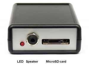
You can connect a speaker by using a 3.5mm mono audio plug. Or use a speaker with plug, like this one from Monacor.
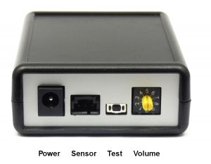
The sensor input is a 3-pin female AMPMODU MTE connector. Pin 2 is connected to D6 of Adalogger and has 10K to GND. Pin 3 is connected to 3V3. If your sensor has a switch as output, it can be connected to pin 2 and 3. To connect a sensor to this input, you can use for example cable assembly 1-2267795-2 from TE Connectivity.
To power the audio player 9 Vdc to 24 Vdc can be used with 1 A max. A standard power supply with a 5.5×2.1mm, center-positive barrel jack can be used. The power input is protected against reverse voltage and has a current limiting fuse.
Programming
The first program you can use is the ArduinoSound SDWaveFile example. This reads a wave file from the SD card and plays it using the I2S interface to the I2S Amp Breakout board.
The file on the SD card for this example should have the name MUSIC.WAV. You can convert many sound files to a wav-file by using for example Audacity. In Audacity use as output file WAV (Microsoft) Signed 16-bit PCM.
Use a micro USB cable to connect Adalogger to your PC, load the example, open the serial monitor and you will hear the sound file. To setup the Arduino IDE for Adalogger, see the website of Adafruit.
Example 2 plays 6 audio tracks, named track001.wav, track002.wav, and so on. At each push on test button or high at sensor input one track is played. At the next push or high the next track is played.
The rotary switch is used to adjust volume and the LED is on during playing.
/*

*** Audio Player Example 2 for ATE-550 from Antratek Electronics ***

Based on Arduino Sound library and WavePlayback example on arduino.cc. (= Example 1 for ATE-550)

Created in 2023 by André Veenstra

This example plays 6 audio tracks. At each push on test button or high at sensor input
one track is played. At the next push or high the next track is played, and so on.
The rotary switch is used to adjust volume and the LED is on during playing.

*/

#include <SD.h>
#include <ArduinoSound.h>

// filename of wave file to play
const char filename1[] = "track001.wav";
const char filename2[] = "track002.wav";
const char filename3[] = "track003.wav";
const char filename4[] = "track004.wav";
const char filename5[] = "track005.wav";
const char filename6[] = "track006.wav";


// variable representing the Wave File
SDWaveFile waveFile;

int counter = 0; //indicates which audio file is next
int test = 5; //number of pin with test button
int inputpin = 6; //number of pin to which input door sensor is connected
int led = 12; // number of pin with led
int prevteststate = 1; //previous test button state
int prevsensorstate = 0; //previous sensor status
int sensoractive = 0; //sensor was activated
int vol = 20; // sound volume
int bcd1 = 15; //pin 1 to 4 of BCD switch for volume
int bcd2 = 16;
int bcd4 = 17;
int bcd8 = 18;

void setup() {
// Open serial communications and wait for port to open:
// Serial.begin(9600);
// while (!Serial) {
// ;
// }

 // initialize pins
 pinMode(LED_BUILTIN, OUTPUT);
 pinMode(led, OUTPUT);
 pinMode(test, INPUT_PULLUP);
 pinMode(inputpin, INPUT);
 pinMode(bcd1, INPUT_PULLUP);
 pinMode(bcd2, INPUT_PULLUP);
 pinMode(bcd4, INPUT_PULLUP);
 pinMode(bcd8, INPUT_PULLUP);

 digitalWrite(LED_BUILTIN, HIGH); // to indicate power is on

 // setup the SD card, depending on your shield of breakout board
 // you may need to pass a pin number in begin for SS
// Serial.print("Initializing SD card...");
 if (!SD.begin(4)) {
// Serial.println("initialization failed!");
 digitalWrite(led, HIGH);
 while (1); // do nothing, led will stay on to indicate SD card is missing
 }
 else {
// Serial.println("initialization done.");
 digitalWrite(led, HIGH);
 delay(500); // short led flash indicates that player is initialized correctly
 digitalWrite(led, LOW);
 }
 // check if the I2S output can play the first wave file
 waveFile = SDWaveFile(filename1);
 if (!AudioOutI2S.canPlay(waveFile)) {
// Serial.println("unable to play wave file using I2S!");
 digitalWrite(led, HIGH);
 while (1); // do nothing, led will stay on to indicate valid file is missing
 }
}


void loop() {
 // check if playback is still going on
 if (!AudioOutI2S.isPlaying()) {
 // playback has stopped
 digitalWrite(led, LOW); // turn the LED off
// Serial.println("playback stopped");
 if (digitalRead(inputpin) == HIGH && prevsensorstate == 0) {
 delay(100); //wait 0.1 sec after sensor
 prevsensorstate = 1;
 }
 if (digitalRead(inputpin) == LOW && prevsensorstate == 1){ //start playback when status of door sensor changed
 prevsensorstate = 0;
 sensoractive = 1;
 playAudio();
 sensoractive = 0;
 }
 if (digitalRead(test) == HIGH) {
 prevteststate = 1;
 }
 if (digitalRead(test) == LOW && prevteststate == 1){ //start playback when status of test button changed
 prevteststate = 0;
 playAudio();
 }

 }
}

void playAudio() {
 counter++;
// Serial.print("Counter is ");
// Serial.println(counter);
 digitalWrite(led, HIGH); // turn the LED on
 vol = 10; //minimum volume if BCD switch volume is 0
 if (digitalRead(bcd1) == LOW){
 vol = vol + 10;
 }
 if (digitalRead(bcd2) == LOW){
 vol = vol + 20;
 }
 if (digitalRead(bcd4) == LOW){
 vol = vol + 40;
 }
 if (digitalRead(bcd8) == LOW){
 vol = vol + 80;
 }
// Serial.print("Volume is ");
// Serial.println(vol);
 AudioOutI2S.volume(vol);// adjust the playback volume

 if (counter == 1) {
// Serial.println("starting playback file 1");
 waveFile = SDWaveFile(filename1); // start playback 1
 AudioOutI2S.play(waveFile);
 }
 if (counter == 2) {
// Serial.println("starting playback file 2");
 waveFile = SDWaveFile(filename2); // start playback 2
 AudioOutI2S.play(waveFile);
 }
 if (counter == 3) {
// Serial.println("starting playback file 3");
 waveFile = SDWaveFile(filename3); // start playback 3
 AudioOutI2S.play(waveFile);
 }
 if (counter == 4) {
// Serial.println("starting playback file 4");
 waveFile = SDWaveFile(filename4); // start playback 4
 AudioOutI2S.play(waveFile);
 }
 if (counter == 5) {
// Serial.println("starting playback file 5");
 waveFile = SDWaveFile(filename5); // start playback 5
 AudioOutI2S.play(waveFile);
 }
 if (counter == 6) {
// Serial.println("starting playback file 6");
 waveFile = SDWaveFile(filename6); // start playback 6
 AudioOutI2S.play(waveFile);
 counter = 0;
 }
 }
You can test the RTC by using ds3231 example as described on the website of Adafruit.
Example 3 uses the RTC and is a kind of cuckoo clock. Every hour it plays an audiotrack. At one o’clock it plays track001, at two o’clock track002, and so on.
/*

*** Audio Player Example 3 for ATE-550 from Antratek Electronics ***

Based on Arduino Sound library and WavePlayback example on arduino.cc and RTClib->ds3231 demo.

Created in 2023 by André Veenstra

This example is a kind of cuckoo clock. Every hour it plays an audiotrack. At one o'clock it plays track001,
at two o'clock track002, and so on.
At a push on test button or high at sensor input the track of the current hour is played.
The rotary switch is used to adjust volume and the LED is on during playing.

*/

#include <SD.h>
#include <ArduinoSound.h>
#include <Wire.h>
#include "RTClib.h"
RTC_DS3231 rtc;

char daysOfTheWeek[7][12] = {"Sunday", "Monday", "Tuesday", "Wednesday", "Thursday", "Friday", "Saturday"};

// filename of wave file to play
const char filename1[] = "track001.wav";
const char filename2[] = "track002.wav";
const char filename3[] = "track003.wav";
const char filename4[] = "track004.wav";
const char filename5[] = "track005.wav";
const char filename6[] = "track006.wav";
const char filename7[] = "track007.wav";
const char filename8[] = "track008.wav";
const char filename9[] = "track009.wav";
const char filename10[] = "track010.wav";
const char filename11[] = "track011.wav";
const char filename12[] = "track012.wav";

// variable representing the Wave File
SDWaveFile waveFile;

int counter = 0;          //indicates which audio file is next
int test = 5;             //number of pin with test button
int inputpin = 6;         //number of pin to which input door sensor is connected
int led = 12;             //number of pin with led
int prevteststate = 1;    //previous test button state
int prevsensorstate = 0;  //previous sensor status
int sensoractive = 0;     //sensor was activated
int vol = 20;             //sound volume
int bcd1 = 15;            //pin 1 to 4 of BCD switch for volume
int bcd2 = 16;
int bcd4 = 17;
int bcd8 = 18;
int cuckoo = 1;           //number of track to be played
int currenthour = 1;      //current hour

void setup() {
// Open serial communications and wait for port to open:
//  Serial.begin(9600);
//  delay(3000); // wait for console opening

  // initialize pins
  pinMode(LED_BUILTIN, OUTPUT);
  pinMode(led, OUTPUT);
  pinMode(test, INPUT_PULLUP);
  pinMode(inputpin, INPUT);
  pinMode(bcd1, INPUT_PULLUP);
  pinMode(bcd2, INPUT_PULLUP);
  pinMode(bcd4, INPUT_PULLUP);
  pinMode(bcd8, INPUT_PULLUP);

  digitalWrite(LED_BUILTIN, HIGH);  // to indicate power is on

  // setup the SD card, depending on your shield of breakout board
  // you may need to pass a pin number in begin for SS
//  Serial.print("Initializing SD card...");
  if (!SD.begin(4)) {
//    Serial.println("initialization failed!");
    digitalWrite(led, HIGH);
    while (1);  // do nothing, led will stay on to indicate SD card is missing
  }
  else {
//    Serial.println("initialization done.");
  digitalWrite(led, HIGH);
  delay(500);       // short led flash indicates that player is initialized correctly
  digitalWrite(led, LOW);
  }
  // check if the I2S output can play the first wave file
  waveFile = SDWaveFile(filename1);
  if (!AudioOutI2S.canPlay(waveFile)) {
//    Serial.println("unable to play wave file using I2S!");
    digitalWrite(led, HIGH);
    while (1); // do nothing, led will stay on to indicate valid file is missing
  }

  if (! rtc.begin()) {
//    Serial.println("Couldn't find RTC");
    digitalWrite(led, HIGH);
    while (1);  // do nothing, led will stay on to indicate RTC is missing
  }

  if (rtc.lostPower()) {
//    Serial.println("RTC lost power, lets set the time!");
    // following line sets the RTC to the date & time this sketch was compiled
    rtc.adjust(DateTime(F(__DATE__), F(__TIME__)));
    // This line sets the RTC with an explicit date & time, for example to set
    // January 21, 2014 at 3am you would call:
    // rtc.adjust(DateTime(2014, 1, 21, 3, 0, 0));
  }
  DateTime now = rtc.now();
  currenthour = now.hour();
}


void loop() {
  // check if playback is still going on
  if (!AudioOutI2S.isPlaying()) {
    // playback has stopped
  digitalWrite(led, LOW);         // turn the LED off
//    Serial.println("playback stopped");
  if (digitalRead(inputpin) == HIGH && prevsensorstate == 0) {
    delay(100);              //wait 0.1 sec after sensor
    prevsensorstate = 1;
  }
  if (digitalRead(inputpin) == LOW && prevsensorstate == 1){   //start playback when status of door sensor changed
    prevsensorstate = 0;
    sensoractive = 1;
    playAudio();
    sensoractive = 0;
  }
  if (digitalRead(test) == HIGH) {
    prevteststate = 1;
  }
  if (digitalRead(test) == LOW && prevteststate == 1){   //start playback when status of test button changed
    prevteststate = 0;
    playAudio();
  }
  delay(100);                                          //check if there is a new hour
  DateTime now = rtc.now();
  if (now.hour() != currenthour){
    currenthour = now.hour();
    playAudio();
  }
  }
}

void playAudio()  {
    counter++;
//    Serial.print("Counter is ");
//    Serial.println(counter);
    digitalWrite(led, HIGH);         // turn the LED on
    vol = 10;   //minimum volume if BCD switch volume is 0
    if (digitalRead(bcd1) == LOW){
      vol = vol + 10;
    }
    if (digitalRead(bcd2) == LOW){
      vol = vol + 20;
    }
    if (digitalRead(bcd4) == LOW){
      vol = vol + 40;
    }
    if (digitalRead(bcd8) == LOW){
      vol = vol + 80;
    }
//    Serial.print("Volume is ");
//    Serial.println(vol);
    AudioOutI2S.volume(vol);// adjust the playback volume

    DateTime now = rtc.now();

/*    Serial.print(now.year(), DEC);
    Serial.print('/');
    Serial.print(now.month(), DEC);
    Serial.print('/');
    Serial.print(now.day(), DEC);
    Serial.print(" (");
    Serial.print(daysOfTheWeek[now.dayOfTheWeek()]);
    Serial.print(") ");
    Serial.print(now.hour(), DEC);
    Serial.print(':');
    Serial.print(now.minute(), DEC);
    Serial.print(':');
    Serial.print(now.second(), DEC);
    Serial.println();
    Serial.println();
*/
    if (now.hour() > 11) {
      cuckoo = now.hour() - 12;     //change 13-24 hours to 1-12 hours
    }
    if (now.hour() < 12) {
      cuckoo = now.hour();
    }
//    Serial.print(currenthour, DEC);
//    Serial.print('>');
//    Serial.print(cuckoo, DEC);
//    Serial.println();

    if (cuckoo == 1) {
//      Serial.println("starting playback file 1");
      waveFile = SDWaveFile(filename1);   // start playback 1
      AudioOutI2S.play(waveFile);
    }
    if (cuckoo == 2) {
//      Serial.println("starting playback file 2");
      waveFile = SDWaveFile(filename2);   // start playback 2
      AudioOutI2S.play(waveFile);
    }
    if (cuckoo == 3) {
//      Serial.println("starting playback file 3");
      waveFile = SDWaveFile(filename3);   // start playback 3
      AudioOutI2S.play(waveFile);
    }
    if (cuckoo == 4) {
//      Serial.println("starting playback file 4");
      waveFile = SDWaveFile(filename4);   // start playback 4
      AudioOutI2S.play(waveFile);
    }
    if (cuckoo == 5) {
//      Serial.println("starting playback file 5");
      waveFile = SDWaveFile(filename5);   // start playback 5
      AudioOutI2S.play(waveFile);
    }
    if (cuckoo == 6) {
//      Serial.println("starting playback file 6");
      waveFile = SDWaveFile(filename6);   // start playback 6
      AudioOutI2S.play(waveFile);
    }
        if (cuckoo == 7) {
//      Serial.println("starting playback file 7");
      waveFile = SDWaveFile(filename7);   // start playback 7
      AudioOutI2S.play(waveFile);
    }
        if (cuckoo == 8) {
//      Serial.println("starting playback file 8");
      waveFile = SDWaveFile(filename8);   // start playback 8
      AudioOutI2S.play(waveFile);
    }
        if (cuckoo == 9) {
//      Serial.println("starting playback file 9");
      waveFile = SDWaveFile(filename9);   // start playback 9
      AudioOutI2S.play(waveFile);
    }
        if (cuckoo == 10) {
//      Serial.println("starting playback file 10");
      waveFile = SDWaveFile(filename10);   // start playback 10
      AudioOutI2S.play(waveFile);
    }
        if (cuckoo == 11) {
//      Serial.println("starting playback file 11");
      waveFile = SDWaveFile(filename11);   // start playback 11
      AudioOutI2S.play(waveFile);
    }
        if (cuckoo == 0) {
//      Serial.println("starting playback file 12");
      waveFile = SDWaveFile(filename12);   // start playback 12
      AudioOutI2S.play(waveFile);
    }
  }
Enclosure
The Audio Player fits inside a Hammond 1593L enclosure. Front and back panel design are available as PDF, DXF and FPD. You can use FPD format for the program Front Panel Designer.
This enclosure with front and back panels are also available as Antratek ATE-550-KIT.